HYDRAULICS LABORATORY
Hydraulics Laboratory provides carrying out the main experiments in the courses related to hydraulics at the undergraduate level and the experimental studies for the students at the graduate level. Experimental setups have a structure that can meet the demands of the projects with their own funding. There are two main experimental sets in the laboratory; pressure pipe systems and open channel test device. A detailed description of these test sets is given below.
Pressurized Pipe System
The setup mainly focuses on the friction and local losses (expansion, contraction, branching, valve losses) in the pressure pipes. Besides, series and parallel connected pump flow, flow in horizontal and vertical pipes, variations in velocity, piezometric measurements, sprinkler irrigation demonstrations (spring flow rate effect, etc.) and weir flow experiments can be done with this setup at undergraduate and graduate levels (Figure 1).
Physical condition:
- The setup is operating. It requires a water tank for continuous water supply.
.jpg) |
Figure 1: Pressurized pipe system setup
|
.jpg) |
.jpg) |
.jpg) |
Open Channel Test Setup
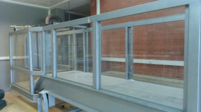
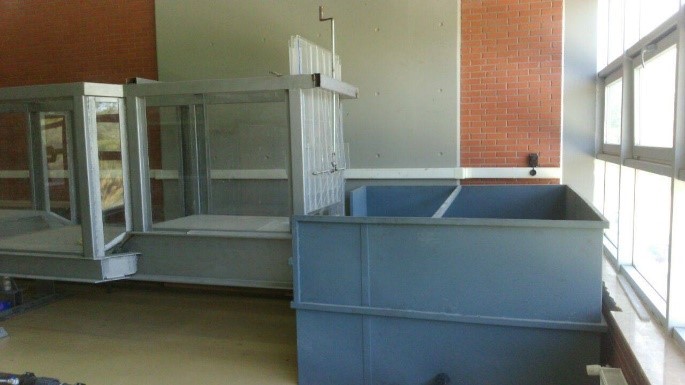
The open channel test setup is designed to conduct experiments for undergraduate and graduate level having steady flow or unstable flows, uniform flow or non-uniform flow, sudden expansion, sudden contraction, step and drop effects, channel slope changes and gate effects. A wave generator is also available for graduate research. According to the test, some of the desired parts can be removed and some can be installed (Figure 2).
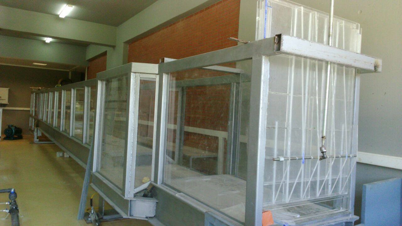 |
Figure 2: Open channel test setup
|
 |
 |
Physical condition:
• Tests can be carried out by placing equipment according to the desired test.
• In order to carry out experiments where continuous flow is required, it requires water tank and installed electrical power.
Energy Losses in Pipes Test Apparatus
It is an experimental unit used to show students the losses in pipe systems and the calculation of K coefficient in fittings. It provides 3 different types of elbows on the test unit as well as sudden expansion and contraction of the pipe system.
In the pipeline system which provides instant expansion, the inner diameter of the narrow pipe is 22 mm and the inner diameter of the wide pipe is 28.4 mm.
To measure pressure in the flow, there is a pressure gauge (manometer) with millimetre water column indicator to make piezometric measurement consisting of 11 thin pipes on the stand. At the outlet of the piping system, there is a valve for adjusting the flow rate to not to cause turbulence in flow and simply for opening and closing. On top of the water column type manometers, there is a glass tube with a valve connected to each other to apply constant pressure to each column. In general, the experimental set shows the comparison between theory and practice.
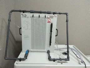 |
Figure 3. Energy Losses in Pipes Test Apparatus |
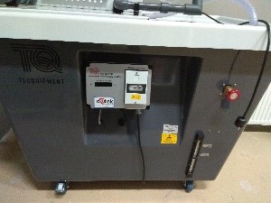 |
Figure 4. Hydraulic Storage and Hydraulic Bench |
Flow Measurement and Bernoulli Equation Test Apparatus
The experiment set is connected to the hydraulic bench which is the main unit. It is used for flow measurement and representation of Bernoulli equation. There are 11 water column types on the panel with a scaled manometer between 0-380 mm. It can make 9 different pressure measurements through the experiment set. Pressure measurements are made in the venturi tube, orifice plane and rotameter unit. It can also be used to show pressure losses in sudden expansions and 90º breaks. The flow rate in the module is maximum 28 l / min.
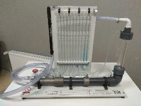 |
Figure 5. Flow Measurement and Bernoulli Equation Test Apparatus |